SmartChamber-3D
Home
Donate
Get a Free Activation Code
  • English
  • 简体中文
Home
Donate
Get a Free Activation Code
  • English
  • 简体中文
  • Introduction
  • Quick Start
  • Hardware

    • Source Files
    • PCB Fabrication
    • Bill of Materials (BOM)
    • Soldering Assistant

      • Main Control Board
      • Heater Board
    • Assembly Instructions
    • Hardware Design Concepts and Principles
    • Hardware wiring diagram
  • Software

    • Function Description
    • Control Logic and Functional Details
    • Firmware Download
    • Firmware Flashing
    • Firmware activation
  • 3D printed parts

    • Introduction
    • Bill of Materials (BOM)
    • Main Frame Installation
    • Modules

      • Module – Source Files
      • Module – Main Controller
      • Module – Exhaust Fan
      • Module – Power Input
      • Module – Drawer
      • Module – Pegboard
      • Module – Blank
      • Module - LOGO
  • FAQ
  • DONATE

Main Frame Installation

Main Frame

Print using PETG

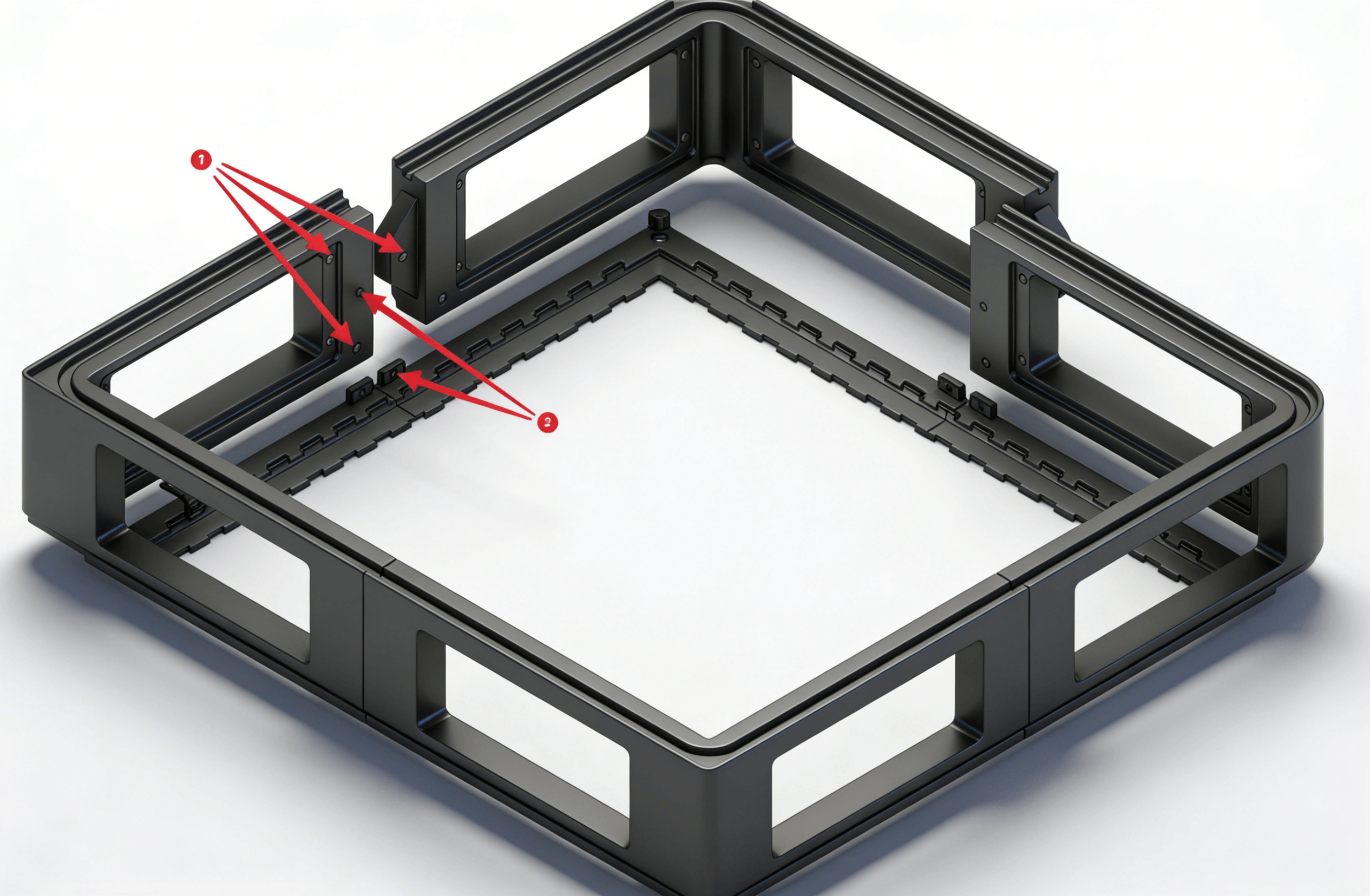
  1. Install in all larger holes: Heat-set insert M3 Ă— 5 Ă— 4.2
  2. Install in all smaller holes: Phillips flat head screw M3 Ă— 6

P2S Heating Module

PETG, ABS, PA, or other materials may be used—the higher the material’s heat resistance, the better

  1. Heat-set insert M3 Ă— 5 Ă— 4.2
  2. Flat self-tapping screw M3 Ă— 6 (mounts inside the left side of the P2S enclosure)
  3. Phillips flat head screw M3 Ă— 6

P1S Heating Module

Install it on the right side inside the P2S enclosure, and secure it using 3M double-sided tape or removable adhesive tape.

  1. Heat-set insert M3 Ă— 5 Ă— 4.2
  2. Phillips flat head screw M3 Ă— 6

Installation Tips

  • Press heat-set inserts slowly with a soldering iron to avoid deforming holes.
  • Install the main frame before other modules for easier assembly.
Last Updated: 3/16/26, 2:51 PM
Contributors: physton
Prev
Bill of Materials (BOM)
Developed by Phyton.com
CC BY-NC-SA 4.0 — Free to use, modify, and share for non-commercial purposes with attribution and same license.