Assembly Instructions
This page explains the main control board interfaces, module connections, and basic assembly checks. It is recommended to verify each item after soldering.
Main Control Board
Connector Map
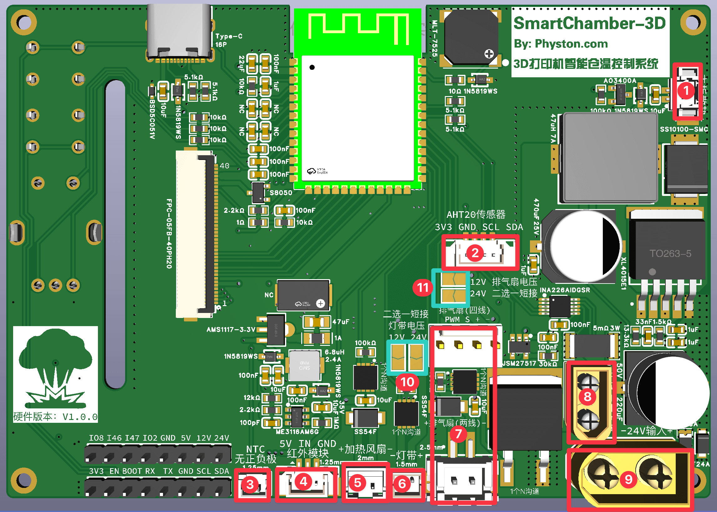
| No. | Connector | Description |
|---|---|---|
| 1 | MX1.25 2P | Connect the main control board cooling fan. Pay attention to the polarity (+/−). |
| 2 | MX1.25 4P | Connect the AHT20 sensor module. Pay attention to the wire order. |
| 3 | MX1.25 2P | Connect the heater plate NTC thermistor. Polarity does not matter. |
| 4 | MX1.25 3P | Connect the PIR motion sensor module. Pay attention to the wire order. |
| 5 | PH2.0 2P | Connect the heater fan. Pay attention to the polarity (+/−). |
| 6 | ZH1.5 2P | Connect the LED strip. Pay attention to the polarity (+/−). |
| 7 | XH2.54 2P / 2510 4P | Connect either a 2-wire or 4-wire exhaust fan (choose one). 4-wire fans use PWM speed control, 2-wire fans use DC voltage control, 4-wire fans are recommended. |
| 8 | XT30 | Connect the heater plate. Polarity does not matter. |
| 9 | XT60 | Power input. Pay attention to the polarity (+/−). |
| 10 | LED strip supply voltage | 12V/24V selectable. Solder the corresponding jumper pads according to your selected voltage. |
| 11 | Exhaust fan supply voltage | 12V/24V selectable. Solder the corresponding jumper pads according to your selected voltage. |
Voltage Selection Pads
- Do not solder both voltage pads at the same time.
- After soldering, use a multimeter to check whether the 12 V and 24 V lines are short-circuited.
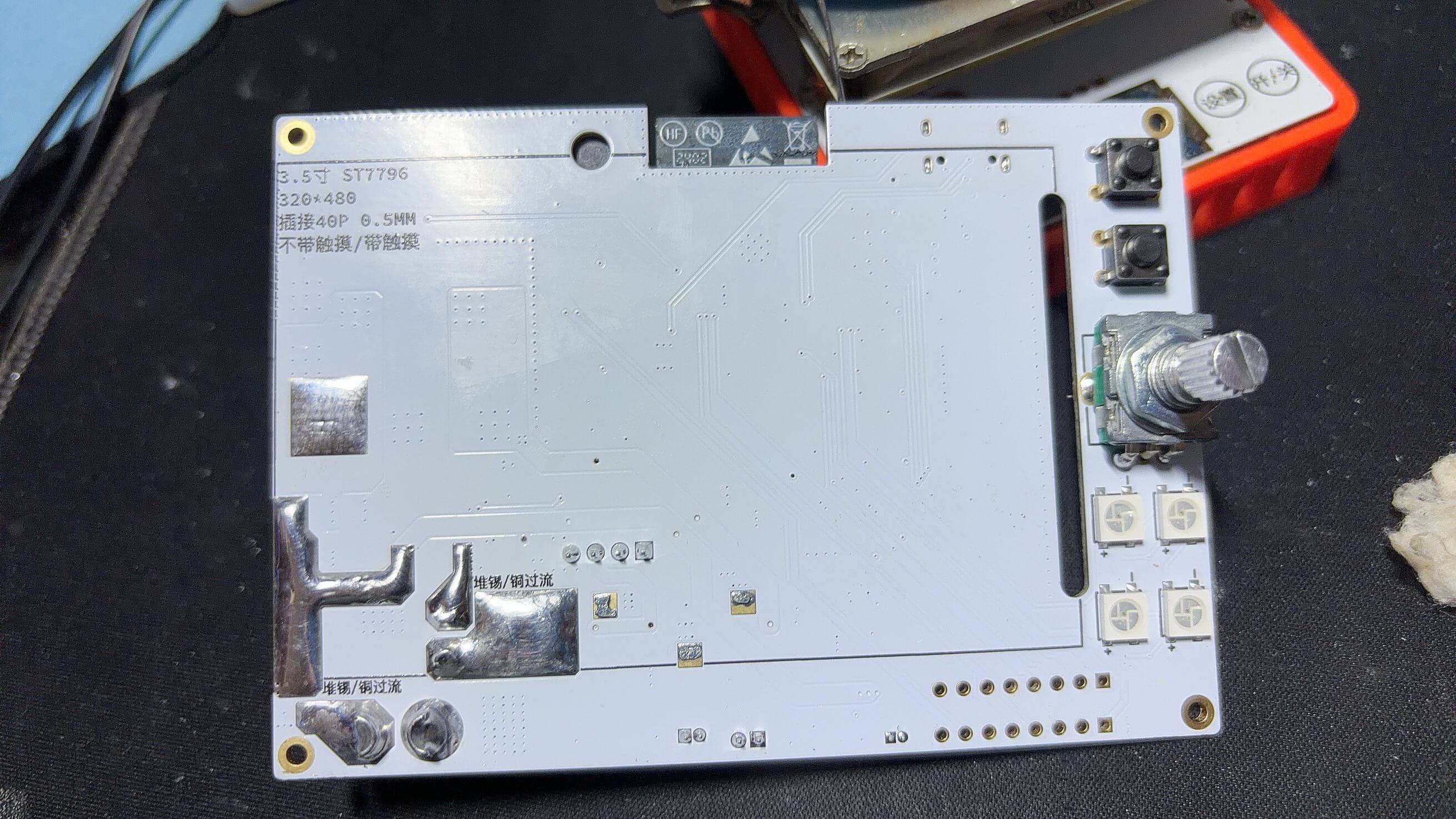
Reserved Pin Headers
The two 1×8P pin headers reserved on the main control board do not need to be soldered. Soldering them will interfere with the cooling fan installation. They are reserved for future feature expansion.
Post-Assembly Checks
- Power the board with USB only and confirm the screen turns on.
- Enter the settings page and test touchscreen input and the EC11 encoder.
- After connecting 24V, confirm the LED strip and fans rotate normally.
- Before testing the heater plate, ensure over-temperature and over-current protection values are set correctly.
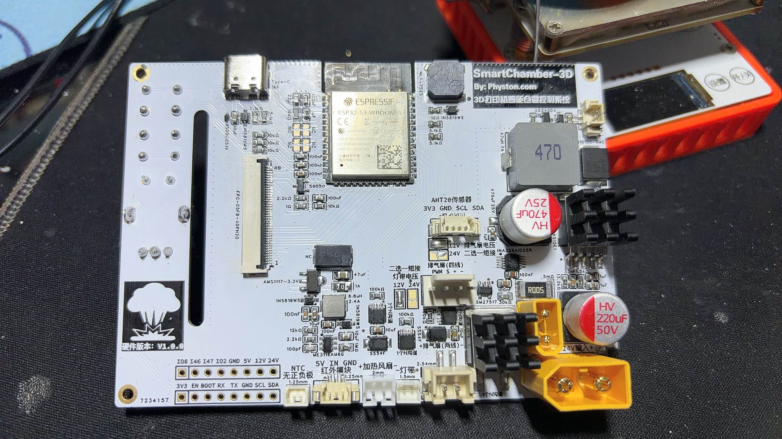
Real Shot Image
PIR Module
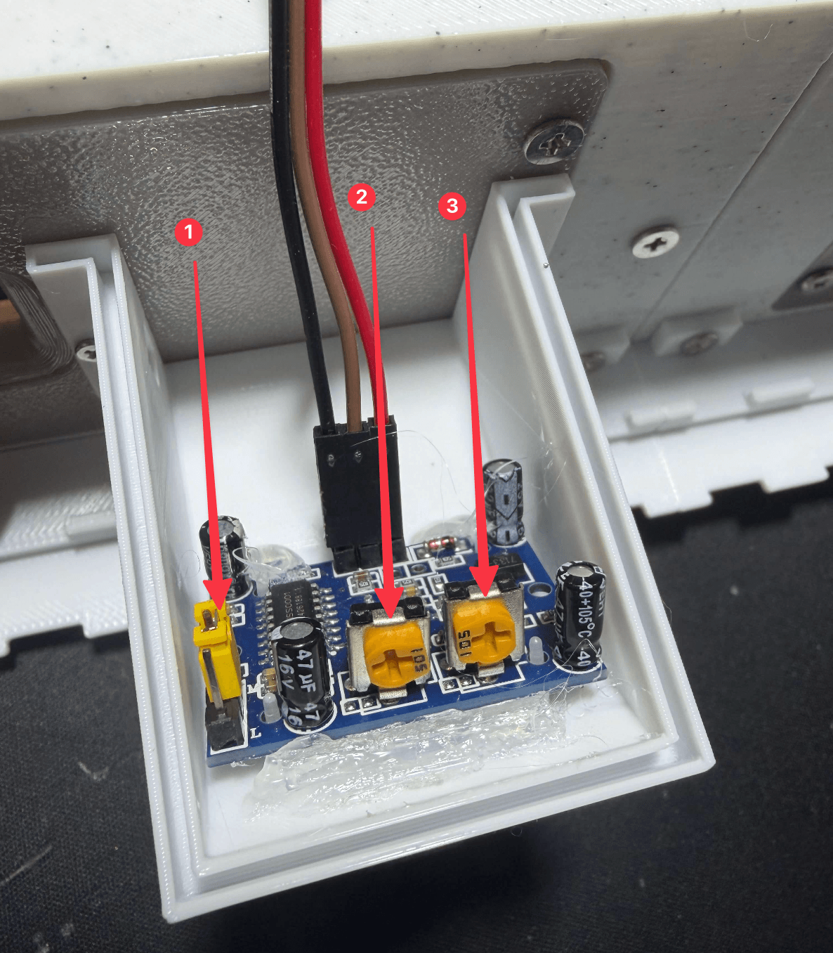
- Set the jumper to
Hmode. - Turn the sensitivity adjustment clockwise to the maximum.
- Turn the delay time adjustment counter-clockwise to the minimum.