Hardware wiring diagram
Image
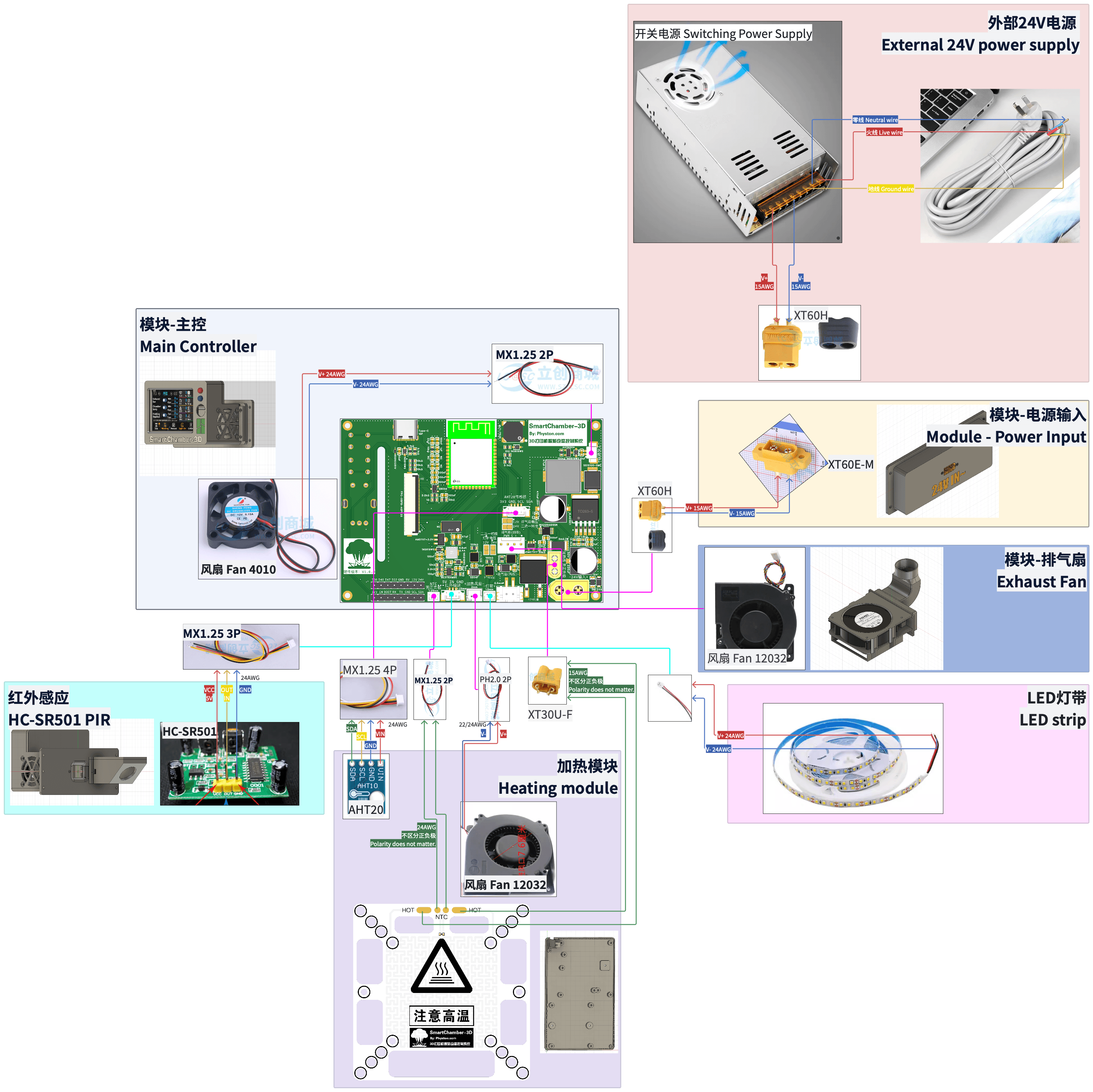
Wiring Notes
- 24V enters via XT60, then is distributed to the main control board and heater plate.
- Sensors and fans connect to the designated headers on the main control board.
- 4-wire exhaust fans use PWM control; 2-wire exhaust fans use DC control.
Suggested Wiring Order
- Connect low-voltage signal lines and sensors first.
- Then connect fans and the LED strip.
- Finally connect the 24V power input and heater plate.
Common Wiring Mistakes
- Reversed fan polarity leading to no rotation.
- Incorrect LED strip voltage pad selection.
- Reversed 24V power polarity causing component damage.